Time for another column as we enter the Student Formula season, and the new Formula One season as the Brawn GP cars will start from the front row in Melbourne later today. It looks like an interesting season.
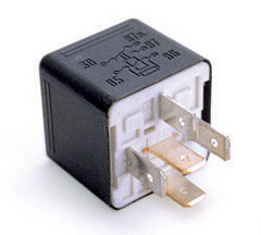
I was invited to drive a FSAE car last weekend, something I was looking forward to as I haven’t had a drive for quite a while, so I was disappointed when the car wouldn’t start. Investigation isolated the fuel pump relay as being the cause. The team leader was surprised as the relay was new. He had another new relay in the spares kit and fitted it, but the engine still wouldn’t start.
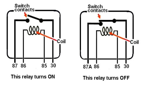
While the team again searched for a wiring gremlin, I casually inspected the discarded relay and the cause of the problem was immediately evident. The switched terminal on the relay was marked ‘87A’. An ‘87A’ relay is one that turns OFF, that is, disconnects the circuit. When I explained this to the team members present it was clear they had no idea what I was talking about! Their electrical expert was not present.
 I borrowed the correct relay from my car (one with a terminal 87 rather than 87A) and with this fitted the car started but would not pull under power. This was the reason the relay had been replaced in the first place as the team guessed that was the problem. What happens if a problem like that crops up in competition? It would certainly ruin your years work if you cannot quickly trouble shoot the issue.
Thinking about some of the dreadful electrical work I have seen on team cars, I thought it might be a good idea to explain some electrical basics in a language that non electrical engineers can understand. If you are an electrician or electrical engineer, you can leave right now because I am not and some of the stuff I am about to say may well be heretical! Along the way I will explain how we troubleshot the problem, located the cause and fixed it so I could have my drive.
Firstly, I am going to speak simply of 12 Volts and 0 Volts here even though the actual voltages may be slightly higher or lower. How much ‘slightly higher or lower’ I will discuss later.
Firstly, some basic electric facts often totally unknown by mechanical engineers but which are very important to understand.
The most simple of electrical circuits requites only a power supply (battery), an electrical load (in this simplified explanation we will use a light) and wiring to connect the lad to the battery on both the power and ground sides.
 If the voltage is measured on the + side of the load, it should be 12 Volts. When measured after the load, it should be, must be, 0 Volts! Regardless of the size of the load the voltage drop across that load should be total. About .2V is acceptable voltage drop.
In the 19th century, a Gustav Kirchhoff proved that the voltage drop in a circuit was relative to the resistances (loads) in that circuit.
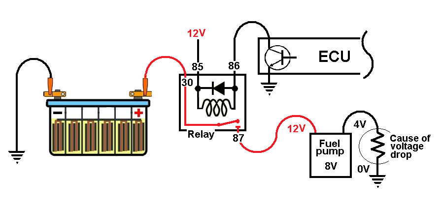
So, a series circuit with two equal loads would cause the voltage to drop to 6 volts between the loads which share the voltage pressure. The second ‘load’ in a circuit can be a resistance in the ground circuit, and this was the case with the car I was to drive. The guys repeatedly measured voltage at the fuel pump where there was a full 12 Volts. When the voltage was measured ACROSS the fuel pump the multimeter showed 8 Volts! No wonder the engine would not perform at higher RPM, the fuel pump could not deliver full flow and pressure.
The car concerned was built on a composite chassis, so the team had used a full earth return circuit. A poor connection was found in this circuit, only a few Ohms, but enough to cause the problem.
Kirchhoff showed us that the voltage drop is not caused by the size of the resistance, but by the relationship between the resistances. This is shown in the diagram where a tiny resistance of half an Ohm in the ground circuit has halved the voltage to a light!
The electrical engineering gurus use the phenomenon of the voltage drop across the load to switch heavy loads (Fuel pump being typical) by a relay. A relay permits them to switch a high current circuit from a low current switch without damage. In a relay, the switching load is the coil around the electro-magnet. Typically, these coils have a resistance of about 80 Ohms and so pass very little current (about .15 Amps).
The usual design has these powered on one side and then switched to ground on the other by a transistor in the ECU. This way the ECU does not have to carry the heavy current of the fuel pump (up to 6 Amps).
It is easy to blame the electronics when things go wrong, but very often the blame lies with the simple electrics, as it was in this case.
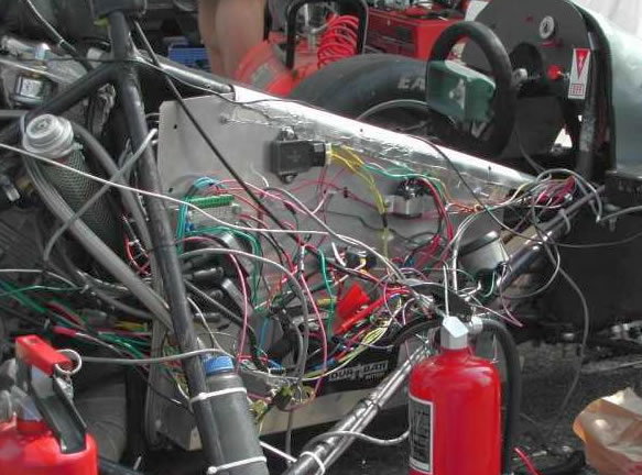
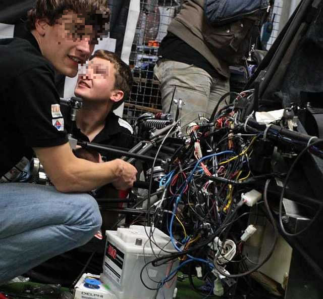
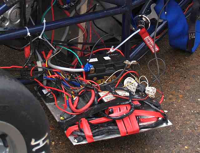
Pat’s Design Error of the Month
Obviously, this months Design Error is related to wiring issues. Believe me, I didn’t have to go far to find examples. Tell me, what are the chances of any of these cars getting to the finish of an event?
Until next time, good luck in building and testing your car.
Regards