
Another month passes by and congratulations are again due to Stuttgart for their victory in Italy. This is a noteworthy achievement for a team in their second year. Three events in 2007 for two wins and a second at Formula Student in the UK behind RMIT! That is an awesome effort. Again, congratulations to all concerned.
Last month I promised that the next column would be written for teams about to design new cars (as opposed to legacy cars) for 2008.
With the FS/FSAE season nearly finished for the year, it is interesting to look at what is being written about the events in the press and what the Design Judges are saying.
Two main topics emerge, and I will talk about both. Firstly there is the issue of who actually designs the car, the team or the computer? The ‘art’ of design is being lost in the soulless brain of computers, and in the process some really beginner’s mistakes are being made.
An experienced Design Judge or engineer casts his eye over many chassis and remarks “That’s GTB”! GTB? Going To Break! The usual response from the student designer is: “Oh no sir, the FEA and other computer stress analysis shows…. etc etc etc…..” Usually, the chassis breaks, just where the old fogy said it would.

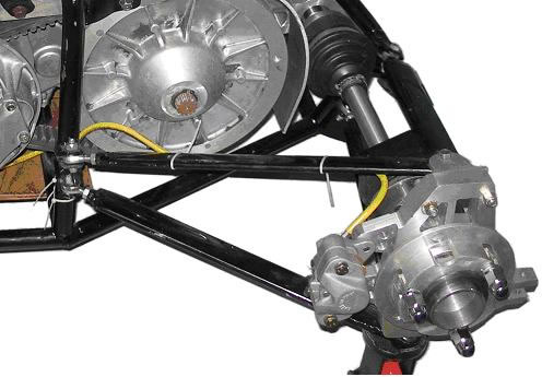
Here is a typical example, a lower wishbone pivot broken out of the chassis.
So, what do these experienced eyes see that is not obvious to the student design team and their very expensive analysis software programs?
Well, the experienced eye looks at the load paths, those sometimes circuitous routes through which the forces are fed through the car. Students sometimes smile when they see me push on a roll hoop. They think I am checking the roll stiffness, but this is not the case. The roll stiffness can be altered with a simple anti-roll bar adjustment, so pushing on the roll hoop will not tell me very much.
What I am actually doing is envisaging where the cornering forces go. I find it easier to see this when I apply an imaginary corning force and se the path to where this force is reacted….down at the tyre contact patch. Let me tell you, some of those load paths are very indirect. I also look at how other loads are reacted in the chassis. Where does the brake torque go? Where does the engine torque go? Where is the drivers mass reacted? How is the brake pedal force reacted? Not just at the pedal end, but also at the other end where the driver is supported. The stiffest pedal box is no good if the seat back flexes!
These forces don’t just evaporate, they are all eventually reacted at the tyre contact patch…..but how does the force go there? Sending loads around corners or through offsets is not good design. Reacting these loads in shear is not good design. Reacting these loads through thin sheet metal brackets is not good design. Reacting these loads into thin air is dreadful design, yet we see all these things in every event……often on cars from very experienced teams.
When a load must be sent around a corner, such as via suspension bell-cranks, the vector forces must be understood and accommodated. Intuitive design doesn’t just use a thicker bolt or an ugly great bracket. Intuitive design elegantly reacts those loads in such a way that the artistry makes the old fogy Design Judge smile.
Unfortunately, computers don’t see those load paths very well, certainly not as well as the authors would have you believe. They are powerful and useful tools, but the tool should never employ the craftsman. The software doesn’t design the car.
Another example of poor load paths. Look at how the rear brake torque is reacted into the chassis.
The second issue I want to address is that the chassis design comes last!
Every year we see cars where the suspension, steering controls etc have all been adapted to a pre existing chassis.
Only this week I was told by a team that they would like to run their lower wishbones parallel to the ground, and they would like to feed the forces at the inner end into the chassis nodes formed where the base and side of the chassis met, but if they did that they would end up with over 100mm ground clearance. So they have steeply sloped wishbones that compromises their camber gain and track control. They haven’t figured it out yet, but they will also have serious bump steer.
Had the design logic been in the correct order, then surely the suspension design would have come first?
Another common example of proof that the designer didn’t oversee the entire program is the commonly seen error of having the axles travel through a totally uncomplimentary arc to the rear suspension. Does someone prior to the Design Judge not look and say “Hey, you can’t do that”?
When a team enter all the hard bits, all the rules requirements and all the bits needed to transport a driver around the FS race track, then the chassis becomes a ‘join the dots’ exercise, and a degree of art and intuitive engineering can be employed rather than just having the CAD program work it out.
That’s all for this month. Final preparations are under way for FSAE Australasia, so in the next column I will tell you about the technical highlights of that event.
Regards

Pat
Pat’s design error of the month:
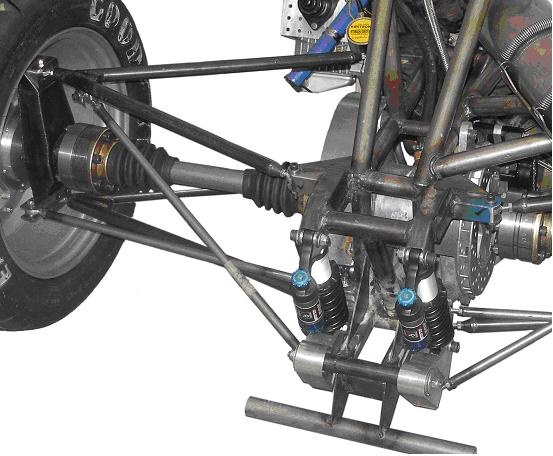
Take a look at this and see how many errors can be seen.
I posted this to illustrate bad load paths, but there are many other errors in design and construction.
There is no way that the pull-rod can operate the bell-cranks through that acute angle. Maybe it works in CAD, but it certainly will not work in the real world, despite the use of expensive needle roller bearings in the bell-crank pivot. This illustrates what I said earlier about vector forces.
Then there is a small matter of toe control and incorrectly used rod ends. This car did not make it to the track.