
Hello all,
60 entrants in FSG 2007! That is absolutely fantastic. FSG is very rapidly becoming the collegiate design competition of choice, especially in Europe. Long may it be!
Another month has passed. It’s hard to believe it is almost March. The time passes so quickly that teams need to be very aware of their time management. One way to waste precious time is to pontificate over design issues in a fruitless quest for a ‘perfect’ design. I’ll let you into a secret. There is no such thing!
Theory
Years ago I heard a saying.
"When the results don’t agree with the theory, then believe the results and form a new theory."
Instead, we tend to distort the results to support a preconceived theory. A conclusion based on an emotional need will not improve your car's performance.
We see this all the time in FSG. Teams get lost pursuing a theory (remember, it’s a ‘theory’ because it is unproven!) to a degree that undermines the entire project. A degree of pragmatism is a good thing here. Remember, not everything can be solved by ‘the computer’, because if you do not know the correct inputs, then you are very unlikely to get the correct outputs.
An example would be a student suspension designer lying awake at night worrying about exact roll centre placement, whilst next door his colleague suffers similar insomnia, but the cause of his is how much Ackermann he should apply. Both would be better off making one of those pragmatic decisions and having a good night’s sleep.
I know this might sound like heresy, but there isn’t an absolutely perfect roll centre, nor is there perfect Ackermann. Like almost every decision on the car, these things are a compromise, and once the problem has been evaluated one of those ‘pragmatic’ decisions can be made and the team can move on. I know team members will have pet theories, and will want the team to adopt them. A strong manager needs to control this trend.
A ‘theory’ about roll centres that crops up regularly is the one about high roll centres not requiring anti roll bars. Yes, a high roll axis reduces the roll couple. It is easy to raise the roll axis above the c/g causing the car to actually bank into a corner. On the surface, this sounds attractive, but by focusing on the high roll centre ‘theory’, the designer didn’t see the other side of the compromise, the jacking effect.
Any car with a roll axis above ground will have some jacking effect. As the roll axis gets higher, so the jacking forces increase. Jacking can be simply described as the effect where the car tries to ‘pole vault’ over the tyre contact patch when cornering forces are applied. An interesting aside… Ferrari design policy for many years dictated the front roll centre at ground level.

Jacking. Notice the rear tyre wear
What about roll centres or roll axes below ground? The opposite of ‘jacking’ is ‘packing’ and a car with subterranean roll centres will pack down under cornering loads. This can cause the car to run out of suspension travel or even ground clearance. There have been cars with a roll axis that has the front R/C below ground and the rear R/C significantly above ground. This steeply sloped axis will cause the rear of the car to jack while the front end packs down. The result is diabolic handling.
So much for the theory! Conventional wisdom dictates an inclined roll axis, with the front roll centre lower than the rear. (Notice I used the word ‘wisdom’ here! That is no mistake). Typically these R/Cs are below 100mm above ground. And with only 50mm wheel travel, can’t move very much if designed sensibly.
The reduced roll couple at the rear leads to balanced handling and any ‘error’ in calculating the roll axis height is easily tuned out with spring rates or motion ratios. The low roll axis means that jacking forces are negligible, and can effectively be ignored.
Meanwhile, our Ackermann insomniac should also make a pragmatic decision. Ackermann ‘errors’ are even easier to tune out by simply making the system adjustable, or adjusting the amount of front wheel toe out.
This ‘tuning’ I am talking about is simply the adjustment of the car to make best use of your design. No-one gets it right first time! A Fender Stratocaster still needs to be tuned to produce its magic sound, while farther down the musical chain, so does a cheap Asian copy. And the cheap guitar, tuned properly can sound better than Eric Clapton’s Strat that has been tuned by…well, been tuned by me.
And that brings up another subject, but one that can wait for another column. That is, money doesn’t guarantee success!
This months Design Error
Just to be different, this month I am going to talk about a piece of good design. This is not a Design Error, rather it is a very nice solution to hub and wheel mount design, although it may have one flaw.
The reason for posting this is that I have been very critical of some hub designs. Having thread roots across the shear face between the hub and wheel, no spigot to centre the wheel on the hub and using tapered wheel nuts seating in aluminium wheel centres are all evidence of poor design.
I don’t know where this hub design comes from, but I like it.
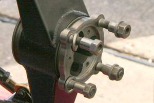
As can be seen, the shear load at the hub face is taken through a small shank on the wheel stud. The wheel nuts are sleeve nuts designed to tighten against the steel hub face whilst applying a measured amount of clamping force to the wheels. The flat washer prevents the nuts galling the wheel centre (especially important with magnesium wheels).
The flaw? What about a centering spigot for the wheel? Well, I hope that is machined into the wheel and sits into the recess in the hub face. If the wheels are being centered by the wheel nuts, then this design is not so nice.
Another nice feature is that the tripod recess is machined right through the live hub. This allows the driveshaft length to be as long as possible, therefore reducing angularity losses, whilst at the same time accepting any driveshaft end plunge caused by suspension movement.
That is enough for this month. Hopefully teams will be back at work getting ready to build their new car. Good luck to all and I look forward to seeing you all in August.
Keep safe
Pat